Context:
BCA was approached by an international leader in medical and safety technology to design an FPGA controller that can interface with numerous systems. The FPGA needed to communicate with two different ADCs (analog to digital converters), as well as accept and send messages over UART, I2C, and SPI. Data received from the ADCs and UART then needed to be packaged and sent to a microcontroller. The microcontroller needed to be able to configure registers on both of the ADCs, as well as send various commands to the FPGA. For improved usability in the field, the FPGA needed to also be field programmable through one of the communication methods.
Solution:
In order to handle the large amount of data coming in from various sources, BCA broke the design into modules to handle each external chip/feature and created a data bus in the FPGA for communication between them. Modules with Master access can read or write to any of the registers addressed in the bus in the other modules. We also created primitive bus arbitration logic to prevent collisions. This bus is used to transfer all data received from the ADCs, as well as commands from I2C and SPI. For the submodules in the device BCA was able to leverage some of our existing IP designs as well as creating the new application specific logic needed.
BCA used a two tier system to achieve field re-programmability. The bitstream is sent to a single port RAM through I2C communication in small chunks. Once the RAM is filled, it is flushed into the appropriate flash memory location. The flash can be read back at any time to confirm the correct information is being loaded. Another I2C command is used to reset the system under the new image.
A large issue this project had to overcome was a strict space constraint. After the final feature was implemented, the compiled design was found to take up around 30% more space then was available on the FPGA. BCA was able to optimize the code to reduce the total amount of logic gates used by 40% without sacrificing features.
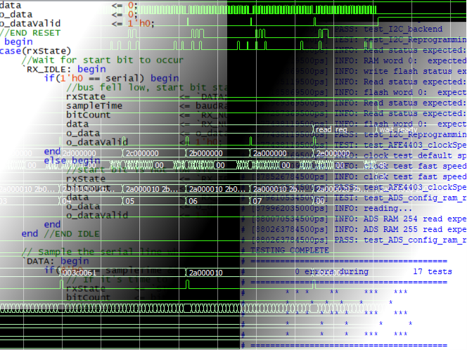
BCA created an automatic test bench leveraging our in house test bench framework to verify the functionality of every module individually and the system as a whole. This test bench verified:
- The correct output stream was observed from a known input
- Timing requirements were met for data transfer
- Internal control registers were successfully updated from external commands
- ADC chips were successfully configured and read at a consistent rate
- Internal Diagnostic tools were behaving correctly
Our team of engineers was able to help our customer achieve a highly optimized design with a full test suite to ensure successful operation and allow fast complete regression testing if changes are needed in the future.